 浏览示例
浏览示例.NET Multi-platform App UI (.NET MAUI) Geometry 类以及派生自它的类可用于描述 2D 形状的几何图形。 Geometry 对象可以是矩形和圆形等简单类型,也可以是由两个或更多个几何对象创建的复合类型。 此外,还可以创建包括圆弧和曲线在内的更复杂的几何图形。
Geometry 类是多个定义不同几何图形类别的类的父类:
- EllipseGeometry,表示椭圆或圆形的几何图形。
- GeometryGroup,表示可将多个几何图形对象组合成单个对象的容器。
- LineGeometry,表示直线的几何图形。
- PathGeometry,表示可由弧线、曲线、椭圆、直线和矩形组成的复杂形状的几何图形。
- RectangleGeometry,表示矩形或正方形的几何图形。
注意
还有一个派生自 GeometryGroup 类的 RoundRectangleGeometry 类。 有关详细信息,请参阅 RoundRectangleGeometry。
Geometry 和 Shape 类的相似之处在于它们均描述 2D 形状,但两者之间存在一些重要区别。 Geometry 类派生自 BindableObject 类,而 Shape 类派生自 View 类。 因此,Shape 对象可以自行呈现并参与布局系统,而 Geometry 对象则不能。 尽管 Shape 对象比 Geometry 对象更易于使用,但 Geometry 对象的用途更为广泛。 尽管 Shape 对象用于呈现 2D 图形,但 Geometry 对象可用于定义 2D 图形的几何区域和定义剪裁的区域。
以下类包含可设置为 Geometry 对象的属性:
- Path 类使用 Geometry 描述其内容。 通过将
Path.Data属性设置为 Geometry 对象,并设置 Path 对象的 Fill 和 Stroke 属性,可以呈现 Geometry。 - VisualElement 类包含类型为 Geometry 的 Clip 属性,用于定义元素内容的轮廓。 当 Clip 属性设置为 Geometry 对象时,只有 Geometry 区域内的区域才可见。 有关详细信息,请参阅使用几何图形剪辑控件。
派生自 Geometry 类的类可分为三个类别:简单几何图形、路径图形和复合图形。
简单几何图形
简单几何图形类包括 EllipseGeometry、LineGeometry 和 RectangleGeometry。 它们用于创建基本几何形状,例如圆形、线条和矩形。 使用 PathGeometry 或将几何对象组合在一起可以创建这些相同的形状以及更复杂的形状,但这些类提供更简单的方法来生成这些基本几何形状。
EllipseGeometry
椭圆几何图形表示椭圆形或圆形的几何图形,由中心点、x 半径和 y 半径定义。
EllipseGeometry 类定义以下属性:
- Center,类型为
Point,表示几何图形的中心点。 - RadiusX,类型为
double,表示几何图形的 x 半径值。 此属性的默认值为 0.0。 - RadiusY,类型为
double,表示几何图形的 y 半径值。 此属性的默认值为 0.0。
这些属性由 BindableProperty 对象提供支持;也就是说,它们可以作为数据绑定的目标,并能进行样式设置。
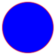
以下示例展示了如何在 Path 对象中创建和呈现 EllipseGeometry:
<Path Fill="Blue"
      Stroke="Red">
  <Path.Data>
    <EllipseGeometry Center="50,50"
                     RadiusX="50"
                     RadiusY="50" />
  </Path.Data>
</Path>
在此示例中,EllipseGeometry 的中心被设置为 (50,50),x 半径和 y 半径均被设置为 50。 这将创建一个直径为 100 个设备无关单位的红色圆圈,圆圈内部涂成蓝色:
LineGeometry
线条几何图形表示线条的几何图形,通过指定线条的起点和终点来定义。
LineGeometry 类定义以下属性:
- StartPoint,类型为
Point,表示线条的起点。 - EndPoint,类型为
Point,表示线条的终点。
这些属性由 BindableProperty 对象提供支持;也就是说,它们可以作为数据绑定的目标,并能进行样式设置。
以下示例展示了如何在 Path 对象中创建和呈现 LineGeometry:
<Path Stroke="Black">
  <Path.Data>
    <LineGeometry StartPoint="10,20"
                  EndPoint="100,130" />
  </Path.Data>
</Path>
在此示例中,从 (10,20) 到 (100,130) 绘制了一个 LineGeometry:
注意
对渲染 LineGeometry 的 Path 的 Fill 属性进行设置不会产生任何效果,因为线条没有内部。
RectangleGeometry
矩形几何图形表示矩形或正方形的几何图形,并由指定矩形或正方形的相对位置、高度和宽度的 Rect 结构定义。
RectangleGeometry 类定义类型为 Rect 的 Rect 属性,表示矩形的尺寸。 此属性由 BindableProperty 对象提供支持,这意味着它可以作为数据绑定的目标,并进行样式设置。
以下示例展示了如何在 Path 对象中创建和呈现 RectangleGeometry:
<Path Fill="Blue"
      Stroke="Red">
  <Path.Data>
    <RectangleGeometry Rect="10,10,150,100" />
  </Path.Data>
</Path>
矩形的位置和尺寸由 Rect 结构定义。 在此示例中,位置为 (10,10),宽度为 150,高度为 100 个设备无关单位:

路径几何图形
路径几何图形描绘可由圆弧、曲线、椭圆、直线和矩形组成的复杂形状的几何图形。
PathGeometry 类定义以下属性:
- Figures,类型为 PathFigureCollection,表示描述路径内容的 PathFigure 对象的集合。
- FillRule,类型为 FillRule,用于确定几何图形中包含的相交区域的组合方式。 此属性的默认值为
FillRule.EvenOdd。
这些属性由 BindableProperty 对象提供支持;也就是说,它们可以作为数据绑定的目标,并能进行样式设置。
有关 FillRule 枚举的详细信息,请参阅 .NET MAUI 形状:填充规则。
注意
由于 Figures 属性是 PathGeometry 类的 ContentProperty,因此不需要通过 XAML 显式设置。
PathGeometry 由 PathFigure 对象集合组成,每个 PathFigure 描述几何图形中的一个形状。 每个 PathFigure 本身都由一个或多个 PathSegment 对象组成,其中每个对象都描述了形状的一个线段。 有多种类型的线段:
- ArcSegment,可在两点之间创建一条椭圆弧。
- BezierSegment,可创建两个点之间的三次方贝塞尔曲线。
- LineSegment,可创建两个点之间的直线。
- PolyBezierSegment,可创建一系列三次方贝塞尔曲线。
- PolyLineSegment,可创建一系列直线。
- PolyQuadraticBezierSegment,可创建一系列二次贝塞尔曲线。
- QuadraticBezierSegment,可创建一条二次贝塞尔曲线。
上述所有类都派生自抽象 PathSegment 类。
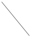
PathFigure 内的多个线段组合成单个几何形状,每个线段的终点是下一个线段的起点。 PathFigure 的 StartPoint 属性指定绘制第一个线段的起点。 每个后续段都从上一段的终点开始。 例如,通过将 StartPoint 属性设置为 10,50 并创建一个 Point 属性设置为 10,150 的 LineSegment,可以定义从 10,50 到 10,150 的竖线:
<Path Stroke="Black">
    <Path.Data>
        <PathGeometry>
            <PathGeometry.Figures>
                <PathFigureCollection>
                    <PathFigure StartPoint="10,50">
                        <PathFigure.Segments>
                            <PathSegmentCollection>
                                <LineSegment Point="10,150" />
                            </PathSegmentCollection>
                        </PathFigure.Segments>
                    </PathFigure>
                </PathFigureCollection>
            </PathGeometry.Figures>
        </PathGeometry>
    </Path.Data>
</Path>
通过使用 PathSegment 对象的组合,以及在 PathGeometry 中使用多个 PathFigure 对象,可以创建更复杂的几何图形。
创建 ArcSegment
ArcSegment 可在两点之间创建一条椭圆弧。 椭圆弧由其起点和终点、x 和 y 半径、x 轴旋转因子、表示弧线是否应大于 180 度的值以及描述弧线绘制方向的值定义。
ArcSegment 类定义以下属性:
- Point,类型为
Point,表示椭圆弧的端点。此属性的默认值为 (0,0)。 - Size,类型为
Size,表示圆弧的 x 和 y 半径。此属性的默认值为 (0,0)。 - RotationAngle,类型为
double,表示椭圆绕 x 轴旋转的度数。 此属性的默认值为 0。 - SweepDirection,类型为 SweepDirection,指定圆弧的绘制方向。 此属性的默认值为
SweepDirection.CounterClockwise。 - IsLargeArc,类型为
bool,指示圆弧是否应大于 180 度。 此属性的默认值为false。
这些属性由 BindableProperty 对象提供支持;也就是说,它们可以作为数据绑定的目标,并能进行样式设置。
注意
ArcSegment 类不包含圆弧起点的属性。它仅定义它表示的圆弧的终点。 圆弧的起点是将 ArcSegment 添加到的 PathFigure 的当前点。
SweepDirection 枚举定义下列成员:
- CounterClockwise,指示以逆时针方向绘制弧线。
- Clockwise,指示以顺时针方向绘制弧线。
以下示例演示了如何在 Path 对象中创建和呈现 ArcSegment:
<Path Stroke="Black">
    <Path.Data>
        <PathGeometry>
            <PathGeometry.Figures>
                <PathFigureCollection>
                    <PathFigure StartPoint="10,10">
                        <PathFigure.Segments>
                            <PathSegmentCollection>
                                <ArcSegment Size="100,50"
                                            RotationAngle="45"
                                            IsLargeArc="True"
                                            SweepDirection="CounterClockwise"
                                            Point="200,100" />
                            </PathSegmentCollection>
                        </PathFigure.Segments>
                    </PathFigure>
                </PathFigureCollection>
            </PathGeometry.Figures>
        </PathGeometry>
    </Path.Data>
</Path>
在以下示例中,从 (10,10) 到 (200,100) 绘制了一个椭圆弧。
创建 BezierSegment
BezierSegment 可创建两个点之间的三次方贝塞尔曲线。 一条三次方贝塞尔曲线由四个点定义:一个起点、一个终点和两个控制点。
BezierSegment 类定义以下属性:
- Point1,类型为
Point,表示曲线的第一个控制点。 此属性的默认值为 (0,0)。 - Point2,类型为
Point,表示曲线的第二个控制点。 此属性的默认值为 (0,0)。 - Point3,类型为
Point,表示曲线的终点。 此属性的默认值为 (0,0)。
这些属性由 BindableProperty 对象提供支持;也就是说,它们可以作为数据绑定的目标,并能进行样式设置。
注意
BezierSegment 类不包含曲线起点的属性。 曲线的起点是将 BezierSegment 添加到的 PathFigure 的当前点。
三次方贝赛尔曲线的两个控制点行为像磁铁一样,朝着自身方向吸引本应为直线的部分,从而形成曲线。 第一个控制点影响曲线的起始部分。 第二个控制点影响曲线的结束部分。 曲线不一定要经过任何一个控制点。 实际上,每个控制点都会将其所在部分的直线向自身移动,但不会穿过自身。
以下示例展示了如何在 Path 对象中创建和呈现 BezierSegment:
<Path Stroke="Black">
    <Path.Data>
        <PathGeometry>
            <PathGeometry.Figures>
                <PathFigureCollection>
                    <PathFigure StartPoint="10,10">
                        <PathFigure.Segments>
                            <PathSegmentCollection>
                                <BezierSegment Point1="100,0"
                                               Point2="200,200"
                                               Point3="300,10" />
                            </PathSegmentCollection>
                        </PathFigure.Segments>
                    </PathFigure>
                </PathFigureCollection>
            </PathGeometry.Figures>
        </PathGeometry>
    </Path.Data>
</Path>
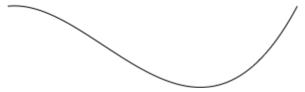
在以下示例中,从 (10,10) 到 (300,10) 绘制了一条三次方贝塞尔曲线。 该曲线有两个控制点,分别位于 (100,0) 和 (200,200):
创建 LineSegment
LineSegment 可创建两个点之间的直线。
LineSegment 类定义类型为 Point 的 Point 属性,表示线段的终点。 此属性的默认值为 (0,0),由 BindableProperty 对象提供支持,这意味着它可以作为数据绑定的目标,并能进行样式设置。
注意
LineSegment 类不包含直线起点的属性。 它仅定义终点。 直线的起点是将 LineSegment 添加到的 PathFigure 的当前点。
以下示例展示了如何在 Path 对象中创建和呈现 LineSegment:
<Path Stroke="Black"
      Aspect="Uniform"
      HorizontalOptions="Start">
    <Path.Data>
        <PathGeometry>
            <PathGeometry.Figures>
                <PathFigureCollection>
                    <PathFigure IsClosed="True"
                                StartPoint="10,100">
                        <PathFigure.Segments>
                            <PathSegmentCollection>
                                <LineSegment Point="100,100" />
                                <LineSegment Point="100,50" />
                            </PathSegmentCollection>
                        </PathFigure.Segments>
                    </PathFigure>
                </PathFigureCollection>
            </PathGeometry.Figures>
        </PathGeometry>
    </Path.Data>
</Path>
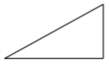
在此示例中,从 (10,100) 到 (100,100) 并从 (100,100) 到 (100,50) 绘制了一条线段。 此外,PathFigure 已封闭,因为其 IsClosed 属性已设置为 true。 其结果是绘制出一个三角形:
创建 PolyBezierSegment
PolyBezierSegment 可创建一条或多条立方贝塞尔曲线。
PolyBezierSegment 类定义类型为 PointCollection 的 Points 属性,表示定义 PolyBezierSegment 的点。 PointCollection 是 Point 对象的 ObservableCollection。 此属性由 BindableProperty 对象提供支持,这意味着它可以作为数据绑定的目标,并进行样式设置。
注意
PolyBezierSegment 类不包含曲线起点的属性。 曲线的起点是将 PolyBezierSegment 添加到的 PathFigure 的当前点。
以下示例展示了如何在 Path 对象中创建和呈现 PolyBezierSegment:
<Path Stroke="Black">
    <Path.Data>
        <PathGeometry>
            <PathGeometry.Figures>
                <PathFigureCollection>
                    <PathFigure StartPoint="10,10">
                        <PathFigure.Segments>
                            <PathSegmentCollection>
                                <PolyBezierSegment Points="0,0 100,0 150,100 150,0 200,0 300,10" />
                            </PathSegmentCollection>
                        </PathFigure.Segments>
                    </PathFigure>
                </PathFigureCollection>
            </PathGeometry.Figures>
        </PathGeometry>
    </Path.Data>
</Path>
在此示例中,PolyBezierSegment 指定了两条立方贝塞尔曲线。 第一条曲线从 (10,10) 绘制到 (150,100),控制点为 (0,0),另一个控制点为 (100,0)。 第二条曲线从 (150,100) 绘制到 (300,10),控制点为 (150,0),另一个控制点为 (200,0):
创建 PolyLineSegment
PolyLineSegment 创建一条或多条线段。
PolyLineSegment 类定义类型为 PointCollection 的 Points 属性,该属性表示定义 PolyLineSegment 的点。 PointCollection 是 Point 对象的 ObservableCollection。 此属性由 BindableProperty 对象提供支持,这意味着它可以作为数据绑定的目标,并进行样式设置。
注意
PolyLineSegment 类不包含线条起点的属性。 线条的起点是将 PolyLineSegment 添加到的 PathFigure 的当前点。
以下示例展示了如何在 Path 对象中创建和呈现 PolyLineSegment:
<Path Stroke="Black">
    <Path.Data>
        <PathGeometry>
            <PathGeometry.Figures>
                <PathFigure StartPoint="10,10">
                    <PathFigure.Segments>
                        <PolyLineSegment Points="50,10 50,50" />
                    </PathFigure.Segments>
                </PathFigure>
            </PathGeometry.Figures>
        </PathGeometry>
    </Path.Data>
</Path>
在此示例中,PolyLineSegment 指定了两行。 第一行是从 (10,10) 到 (50,10),第二行是从 (50,10) 到 (50,50):

创建 PolyQuadraticBezierSegment
PolyQuadraticBezierSegment 可创建一条或多条二次方贝塞尔曲线。
PolyQuadraticBezierSegment 类定义类型为 PointCollection 的 Points 属性,该属性表示定义 PolyQuadraticBezierSegment 的点。 PointCollection 是 Point 对象的 ObservableCollection。 此属性由 BindableProperty 对象提供支持,这意味着它可以作为数据绑定的目标,并进行样式设置。
注意
PolyQuadraticBezierSegment 类不包含曲线起点的属性。 曲线的起点是将 PolyQuadraticBezierSegment 添加到的 PathFigure 的当前点。
以下示例展示了如何在 Path 对象中创建和呈现 PolyQuadraticBezierSegment:
<Path Stroke="Black">
    <Path.Data>
        <PathGeometry>
            <PathGeometry.Figures>
                <PathFigureCollection>
                    <PathFigure StartPoint="10,10">
                        <PathFigure.Segments>
                            <PathSegmentCollection>
                                <PolyQuadraticBezierSegment Points="100,100 150,50 0,100 15,200" />
                            </PathSegmentCollection>
                        </PathFigure.Segments>
                    </PathFigure>
                </PathFigureCollection>
            </PathGeometry.Figures>
        </PathGeometry>
    </Path.Data>
</Path>
在此示例中,PolyQuadraticBezierSegment 指定了两条贝塞尔曲线。 第一条曲线是从 (10,10) 到 (150,50),控制点为 (100,100)。 第二条曲线是从 (100,100) 到 (15,200),控制点为 (0,100):
创建 QuadraticBezierSegment
QuadraticBezierSegment 可在两点之间创建二次方贝塞尔曲线。
QuadraticBezierSegment 类定义以下属性:
这些属性由 BindableProperty 对象提供支持;也就是说,它们可以作为数据绑定的目标,并能进行样式设置。
注意
QuadraticBezierSegment 类不包含曲线起点的属性。 曲线的起点是将 QuadraticBezierSegment 添加到的 PathFigure 的当前点。
以下示例展示了如何在 Path 对象中创建和呈现 QuadraticBezierSegment:
<Path Stroke="Black">
    <Path.Data>
        <PathGeometry>
            <PathGeometry.Figures>
                <PathFigureCollection>
                    <PathFigure StartPoint="10,10">
                        <PathFigure.Segments>
                            <PathSegmentCollection>
                                <QuadraticBezierSegment Point1="200,200"
                                                        Point2="300,10" />
                            </PathSegmentCollection>
                        </PathFigure.Segments>
                    </PathFigure>
                </PathFigureCollection>
            </PathGeometry.Figures>
        </PathGeometry>
    </Path.Data>
</Path>
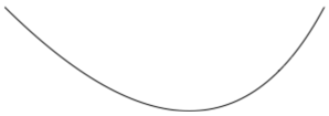
在此示例中,绘制了一条从 (10,10) 到 (300,10) 的二次方贝塞尔曲线。 曲线的控制点为 (200,200):
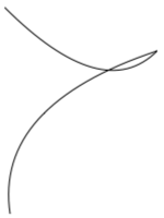
创建复杂几何图形
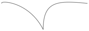
通过使用 PathSegment 对象的组合可以创建更复杂的几何图形。 以下示例使用 BezierSegment、LineSegment 和 ArcSegment 创建形状:
<Path Stroke="Black">
    <Path.Data>
        <PathGeometry>
            <PathGeometry.Figures>
                <PathFigure StartPoint="10,50">
                    <PathFigure.Segments>
                        <BezierSegment Point1="100,0"
                                       Point2="200,200"
                                       Point3="300,100"/>
                        <LineSegment Point="400,100" />
                        <ArcSegment Size="50,50"
                                    RotationAngle="45"
                                    IsLargeArc="True"
                                    SweepDirection="Clockwise"
                                    Point="200,100"/>
                    </PathFigure.Segments>
                </PathFigure>
            </PathGeometry.Figures>
        </PathGeometry>
    </Path.Data>
</Path>
在此示例中,首先使用四个点定义 BezierSegment。 然后,该示例添加 LineSegment,并在 BezierSegment 的终点与 LineSegment 指定的点之间对其进行绘制。 最后,从 LineSegment 的终点到 ArcSegment 指定的点绘制 ArcSegment。
可以通过使用 PathGeometry 内的多个 PathFigure 对象创建更复杂的几何图形。 以下示例从七个 PathFigure 对象创建 PathGeometry,其中一些对象包含多个 PathSegment 对象:
<Path Stroke="Red"
      StrokeThickness="12"
      StrokeLineJoin="Round">
    <Path.Data>
        <PathGeometry>
            <!-- H -->
            <PathFigure StartPoint="0,0">
                <LineSegment Point="0,100" />
            </PathFigure>
            <PathFigure StartPoint="0,50">
                <LineSegment Point="50,50" />
            </PathFigure>
            <PathFigure StartPoint="50,0">
                <LineSegment Point="50,100" />
            </PathFigure>

            <!-- E -->
            <PathFigure StartPoint="125, 0">
                <BezierSegment Point1="60, -10"
                               Point2="60, 60"
                               Point3="125, 50" />
                <BezierSegment Point1="60, 40"
                               Point2="60, 110"
                               Point3="125, 100" />
            </PathFigure>

            <!-- L -->
            <PathFigure StartPoint="150, 0">
                <LineSegment Point="150, 100" />
                <LineSegment Point="200, 100" />
            </PathFigure>

            <!-- L -->
            <PathFigure StartPoint="225, 0">
                <LineSegment Point="225, 100" />
                <LineSegment Point="275, 100" />
            </PathFigure>

            <!-- O -->
            <PathFigure StartPoint="300, 50">
                <ArcSegment Size="25, 50"
                            Point="300, 49.9"
                            IsLargeArc="True" />
            </PathFigure>
        </PathGeometry>
    </Path.Data>
</Path>
在此示例中,单词“Hello”是使用 LineSegment 和 BezierSegment 对象以及单个 ArcSegment 对象的组合绘制的:

复合几何图形
可以使用 GeometryGroup 创建复合几何图形对象。 GeometryGroup 类可根据一个或多个 Geometry 对象创建复合几何图形。 可以将任意数量的 Geometry 对象添加到 GeometryGroup。
GeometryGroup 类定义以下属性:
- Children,类型为 GeometryCollection,指定用于定义 GeometryGroup 的对象。 GeometryCollection 是 Geometry 对象的
ObservableCollection。 - FillRule,类型为 FillRule,指定如何组合 GeometryGroup 内的相交区域。 此属性的默认值为
FillRule.EvenOdd。
这些属性由 BindableProperty 对象提供支持;也就是说,它们可以作为数据绑定的目标,并能进行样式设置。
注意
由于 Children 属性是 GeometryGroup 类的 ContentProperty,因此不需要通过 XAML 显式设置。
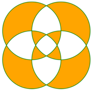
要绘制复合几何图形,请将所需的 Geometry 对象设置为 GeometryGroup 的子级,并使用 Path 对象显示它们。 下面的 XAML 展示了一个示例:
<Path Stroke="Green"
      StrokeThickness="2"
      Fill="Orange">
    <Path.Data>
        <GeometryGroup>
            <EllipseGeometry RadiusX="100"
                             RadiusY="100"
                             Center="150,150" />
            <EllipseGeometry RadiusX="100"
                             RadiusY="100"
                             Center="250,150" />
            <EllipseGeometry RadiusX="100"
                             RadiusY="100"
                             Center="150,250" />
            <EllipseGeometry RadiusX="100"
                             RadiusY="100"
                             Center="250,250" />
        </GeometryGroup>
    </Path.Data>
</Path>
在此示例中,合并了四个具有相同 x 半径和 y 半径坐标,但具有不同中心坐标的 EllipseGeometry 对象。 这会创建四个重叠的圆,由于默认的 EvenOdd 填充规则,圆的内部被填充为橙色:
RoundRectangleGeometry
圆角矩形几何图形表示具有圆角的矩形或正方形的几何图形,由角半径和 Rect 结构(用于指定其相对位置以及高度和宽度)定义。
RoundRectangleGeometry 类派生自 GeometryGroup 类,定义了以下属性:
- CornerRadius,类型为
CornerRadius,是几何图形的角半径。 - Rect,类型为
Rect,表示矩形的尺寸。
这些属性由 BindableProperty 对象提供支持;也就是说,它们可以作为数据绑定的目标,并能进行样式设置。
注意
RoundRectangleGeometry 使用的填充规则是 FillRule.Nonzero。 有关填充规则的详细信息,请参阅填充规则。
以下示例展示了如何在 Path 对象中创建和呈现 RoundRectangleGeometry:
<Path Fill="Blue"
      Stroke="Red">
    <Path.Data>
        <RoundRectangleGeometry CornerRadius="5"
                                Rect="10,10,150,100" />
    </Path.Data>
</Path>
矩形的位置和尺寸由 Rect 结构定义。 在此示例中,位置为 (10,10),宽度为 150,高度为 100 个设备无关单位。 此外,矩形角的圆角半径为 5 个设备无关单位。
使用几何图形进行剪切
VisualElement 类包含类型为 Geometry 的 Clip 属性,用于定义元素内容的轮廓。 当 Clip 属性设置为 Geometry 对象时,只有 Geometry 区域内的区域才可见。
以下示例展示了如何使用 Geometry 对象作为 Image 的剪切区域:
<Image Source="monkeyface.png">
    <Image.Clip>
        <EllipseGeometry RadiusX="100"
                         RadiusY="100"
                         Center="180,180" />
    </Image.Clip>
</Image>
在此示例中,EllipseGeometry 的 RadiusX 和 RadiusY 值为 100,Center 值为 (180,180),被设置为 Image 的 Clip 属性。 将仅显示处于椭圆形区域内的图像部分。

注意
简单几何图形、路径几何图形和复合几何图形都可用于剪切 VisualElement 对象。
其他功能
GeometryHelper 类提供以下帮助程序方法:
- FlattenGeometry,可将 Geometry 平展成一个 PathGeometry。
- FlattenCubicBezier,可将三次方贝塞尔曲线平展到
List<Point>集合中。 - FlattenQuadraticBezier,可将二方次贝塞尔曲线平展到
List<Point>集合中。 - FlattenArc,可将椭圆弧平展到
List<Point>集合中。