本概述介绍如何使用 Windows Presentation Foundation (WPF) Geometry 类描述形状。 本主题还对比了Geometry对象和Shape元素之间的差异。
什么是几何图形?
类 Geometry 和从它派生的类,例如 EllipseGeometry,PathGeometry 和 CombinedGeometry,使你能够描述二维形状的几何。 这些几何描述有许多用途,例如定义要绘制到屏幕的形状或定义命中测试和剪辑区域。 甚至可以使用几何图形来定义动画路径。
Geometry 对象可以是简单对象,如矩形和圆或复合,从两个或多个几何对象创建。 使用PathGeometry和StreamGeometry类可以创建更复杂的几何图形,使你能够描述弧线和曲线。
由于对象 Geometry 是一种 Freezable类型, Geometry 因此提供了多种特殊功能:它们可以声明为 资源,在多个对象之间共享,进行只读,以提高性能、克隆和使线程安全。 有关 Freezable 对象所提供的各种功能的更多信息,请参阅 Freezable 对象概述。
几何图形与形状
和GeometryShape类似乎相似,因为它们都描述了二维形状(例如比较EllipseGeometry和Ellipse例如),但存在重要的差异。
对于一个,类 Geometry 继承自 Freezable 类,而 Shape 类继承自 FrameworkElement。 由于它们是元素, Shape 因此对象可以自行呈现并参与布局系统,而 Geometry 对象则不能。
尽管 Shape 对象比 Geometry 对象更易使用, Geometry 但对象更通用。 Shape虽然对象用于呈现 2D 图形,Geometry但对象可用于定义 2D 图形的几何区域、定义剪裁的区域或定义用于命中测试的区域,例如。
路径形状
一个 Shape 的 Path 类实际上使用一个 Geometry 来描述其内容。 通过设置 Path 的 Data 属性、使用 Geometry 并设置其 Fill 和 Stroke 属性,可以呈现一个 Geometry。
采用几何图形的常用属性
上述部分提到,Geometry 对象可以与其他对象一起使用,以实现各种目的,例如绘制形状、动画和剪辑。 下表列出了具有采用 Geometry 对象的属性的多个类。
| 类型 | 资产 |
|---|---|
| DoubleAnimationUsingPath | PathGeometry |
| DrawingGroup | ClipGeometry |
| GeometryDrawing | Geometry |
| Path | Data |
| UIElement | Clip |
简单几何图形类型
所有几何图形的基类是抽象类 Geometry。 派生自类的 Geometry 类可以大致分为三个类别:简单几何图形、路径几何图形和复合几何图形。
简单的几何图形类包括 LineGeometry, RectangleGeometry以及 EllipseGeometry 用于创建基本几何形状,如线条、矩形和圆圈。
通过指定线条的起点和终点来定义 A LineGeometry 。
使用结构Rect定义 ARectangleGeometry,该结构指定其相对位置及其高度和宽度。 可以通过设置 RadiusX 和 RadiusY 属性来创建圆角矩形。
A EllipseGeometry 由中心点、x 半径和 y 半径定义。 以下示例演示如何创建用于呈现和剪辑的简单几何图形。
这些相同的形状以及更复杂的形状可以使用 PathGeometry 或通过组合几何对象来创建,但这些类提供了一种更简单的方法来生成这些基本几何形状。
以下示例演示如何创建和呈现 LineGeometry。 如前所述, Geometry 对象无法绘制自身,因此该示例使用 Path 形状来呈现线条。 由于线条没有区域,因此设置 Path 属性将不起作用;而是只指定了 Stroke 和 StrokeThickness 属性。 下图显示了示例的输出。
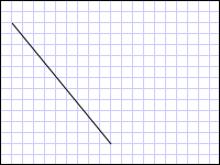
从 (10,20) 绘制到 (100,130) 的 LineGeometry
<Path Stroke="Black" StrokeThickness="1" >
  <Path.Data>
    <LineGeometry StartPoint="10,20" EndPoint="100,130" />
  </Path.Data>
</Path>
LineGeometry myLineGeometry = new LineGeometry();
myLineGeometry.StartPoint = new Point(10,20);
myLineGeometry.EndPoint = new Point(100,130);

Path myPath = new Path();
myPath.Stroke = Brushes.Black;
myPath.StrokeThickness = 1;
myPath.Data = myLineGeometry;
Dim myLineGeometry As New LineGeometry()
myLineGeometry.StartPoint = New Point(10,20)
myLineGeometry.EndPoint = New Point(100,130)

Dim myPath As New Path()
myPath.Stroke = Brushes.Black
myPath.StrokeThickness = 1
myPath.Data = myLineGeometry
下一个示例演示如何创建和呈现EllipseGeometry。 这些示例设置了Center和EllipseGeometry,将它们设置为点50,50,同时将 x 半径和 y 半径均设置为50,这将创建直径为 100 的单位圆。 椭圆的内部是通过将值赋给路径元素的填充属性来绘制的,在本例 Gold 中。 下图显示了示例的输出。
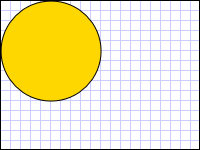
绘制的椭圆几何体在位置 (50,50)
<Path Fill="Gold" Stroke="Black" StrokeThickness="1">
  <Path.Data>
    <EllipseGeometry Center="50,50" RadiusX="50" RadiusY="50" />
  </Path.Data>
</Path>
EllipseGeometry myEllipseGeometry = new EllipseGeometry();
myEllipseGeometry.Center = new Point(50, 50);
myEllipseGeometry.RadiusX = 50;
myEllipseGeometry.RadiusY = 50;

Path myPath = new Path();
myPath.Fill = Brushes.Gold;
myPath.Stroke = Brushes.Black;
myPath.StrokeThickness = 1;
myPath.Data = myEllipseGeometry;
Dim myEllipseGeometry As New EllipseGeometry()
myEllipseGeometry.Center = New Point(50, 50)
myEllipseGeometry.RadiusX = 50
myEllipseGeometry.RadiusY = 50

Dim myPath As New Path()
myPath.Fill = Brushes.Gold
myPath.Stroke = Brushes.Black
myPath.StrokeThickness = 1
myPath.Data = myEllipseGeometry
以下示例演示如何创建和呈现 RectangleGeometry。 矩形的位置和尺寸由 Rect 结构定义。 位置是 50,50 和高度和宽度都是 25,这将创建一个正方形。 下图显示了示例的输出。
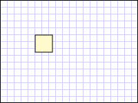
在坐标50,50绘制的RectangleGeometry
<Path Fill="LemonChiffon" Stroke="Black" StrokeThickness="1">
  <Path.Data>
    <RectangleGeometry Rect="50,50,25,25" />
  </Path.Data>
</Path>
RectangleGeometry myRectangleGeometry = new RectangleGeometry();
myRectangleGeometry.Rect = new Rect(50,50,25,25);

Path myPath = new Path();
myPath.Fill = Brushes.LemonChiffon;
myPath.Stroke = Brushes.Black;
myPath.StrokeThickness = 1;
myPath.Data = myRectangleGeometry;
Dim myRectangleGeometry As New RectangleGeometry()
myRectangleGeometry.Rect = New Rect(50,50,25,25)

Dim myPath As New Path()
myPath.Fill = Brushes.LemonChiffon
myPath.Stroke = Brushes.Black
myPath.StrokeThickness = 1
myPath.Data = myRectangleGeometry
以下示例演示如何使用 EllipseGeometry 作为图像的剪辑区域。 使用 Image 200 和 Height 150 定义Width对象。 EllipseGeometry的值为RadiusX 100、RadiusY的值为 75 且Center的值为 100,75 设置为Clip图像的属性。 仅显示椭圆区域内的图像部分。 下图显示了示例的输出。
具有剪裁和不剪裁的图像 graphicsmm_clipexample
用于裁剪图像控件的椭圆几何体
<Image
  Source="sampleImages\Waterlilies.jpg"
  Width="200" Height="150" HorizontalAlignment="Left">
  <Image.Clip>
    <EllipseGeometry
      RadiusX="100"
      RadiusY="75"
      Center="100,75"/>
  </Image.Clip>
</Image>
// Create the image to clip.
Image myImage = new Image();
Uri imageUri =
    new Uri(@"C:\\Documents and Settings\\All Users\\Documents\My Pictures\\Sample Pictures\\Water lilies.jpg", UriKind.Relative);
myImage.Source = new BitmapImage(imageUri);
myImage.Width = 200;
myImage.Height = 150;
myImage.HorizontalAlignment = HorizontalAlignment.Left;

// Use an EllipseGeometry to define the clip region.
EllipseGeometry myEllipseGeometry = new EllipseGeometry();
myEllipseGeometry.Center = new Point(100, 75);
myEllipseGeometry.RadiusX = 100;
myEllipseGeometry.RadiusY = 75;
myImage.Clip = myEllipseGeometry;
' Create the image to clip.
Dim myImage As New Image()
Dim imageUri As New Uri("C:\\Documents and Settings\\All Users\\Documents\My Pictures\\Sample Pictures\\Water lilies.jpg", UriKind.Relative)
myImage.Source = New BitmapImage(imageUri)
myImage.Width = 200
myImage.Height = 150
myImage.HorizontalAlignment = HorizontalAlignment.Left

' Use an EllipseGeometry to define the clip region.
Dim myEllipseGeometry As New EllipseGeometry()
myEllipseGeometry.Center = New Point(100, 75)
myEllipseGeometry.RadiusX = 100
myEllipseGeometry.RadiusY = 75
myImage.Clip = myEllipseGeometry
路径几何图形
类 PathGeometry 及其轻型等效 StreamGeometry 类提供了描述由弧线、曲线和线条组成的多个复杂图形的方法。
一个 PathGeometry 的核心是一个 PathFigure 对象的集合,之所以命名如此,是因为每个图形在 PathGeometry 中描述了一个离散的形状。 每个 PathFigure 对象本身都由一个或多个 PathSegment 对象组成,每个对象都描述该图的一段。
有许多类型的片段。
| 段类型 | DESCRIPTION | 示例: |
|---|---|---|
| ArcSegment | 在两个点之间创建椭圆弧。 | 创建椭圆弧线。 |
| BezierSegment | 在两个点之间创建一个立方贝塞尔曲线。 | 创建立方贝塞尔曲线。 |
| LineSegment | 在两个点之间创建一条线。 | 在 PathGeometry 中创建 LineSegment |
| PolyBezierSegment | 创建一系列立方贝塞尔曲线。 | 请查看PolyBezierSegment类型页。 |
| PolyLineSegment | 创建一系列线条。 | 请参阅PolyLineSegment类型页。 |
| PolyQuadraticBezierSegment | 创建一系列二次贝塞尔曲线。 | 请参阅页面 PolyQuadraticBezierSegment 。 |
| QuadraticBezierSegment | 创建二次贝塞尔曲线。 | 创建二次贝塞尔曲线。 |
内 PathFigure 段合并为单个几何形状,每个线段的终点是下一段的起点。
StartPoint 的 PathFigure 属性指定绘制第一段的起点。 每个后续段从上一段的终点开始。 例如,可以通过将StartPoint属性设置为10,50,并创建一个LineSegment,其Point属性设置为10,150,来定义从10,50到10,150的垂直线。
以下示例创建一个由单个PathFigure和LineSegment元素组成的简单PathGeometry,并使用Path元素显示它。
PathFigure对象的StartPoint设置为10,20,并且定义了一个终点为100,130的LineSegment。 下图显示了此示例所创建的 PathGeometry。

包含单个直线段的路径几何体
<Path Stroke="Black" StrokeThickness="1">
  <Path.Data>
    <PathGeometry>
      <PathGeometry.Figures>
        <PathFigure StartPoint="10,20">
          <PathFigure.Segments>
            <LineSegment Point="100,130"/>
          </PathFigure.Segments>
        </PathFigure>
      </PathGeometry.Figures>
    </PathGeometry>
  </Path.Data>
</Path>
// Create a figure that describes a
// line from (10,20) to (100,130).
PathFigure myPathFigure = new PathFigure();
myPathFigure.StartPoint = new Point(10,20);
myPathFigure.Segments.Add(
    new LineSegment(new Point(100,130),
    true /* IsStroked */ ));

/// Create a PathGeometry to contain the figure.
PathGeometry myPathGeometry = new PathGeometry();
myPathGeometry.Figures.Add(myPathFigure);

// Display the PathGeometry.
Path myPath = new Path();
myPath.Stroke = Brushes.Black;
myPath.StrokeThickness = 1;
myPath.Data = myPathGeometry;
' Create a figure that describes a
' line from (10,20) to (100,130).
Dim myPathFigure As New PathFigure()
myPathFigure.StartPoint = New Point(10,20)
myPathFigure.Segments.Add(New LineSegment(New Point(100,130), True)) ' IsStroked

''' Create a PathGeometry to contain the figure.
Dim myPathGeometry As New PathGeometry()
myPathGeometry.Figures.Add(myPathFigure)

' Display the PathGeometry.
Dim myPath As New Path()
myPath.Stroke = Brushes.Black
myPath.StrokeThickness = 1
myPath.Data = myPathGeometry
值得将此示例与前面的 LineGeometry 示例进行对比。 用于 PathGeometry 的语法比简单 LineGeometry 的语法更加详细,在这种情况下,更合理的选择可能是使用 LineGeometry 类,但 PathGeometry 的详细语法允许构建极其复杂和精细的几何区域。
可以使用对象组合 PathSegment 来创建更复杂的几何图形。
下一个示例使用一个 BezierSegment、一个 LineSegment和一个 ArcSegment 来创建形状。 第一个示例创建一个立方贝塞尔曲线是通过定义四个点:一个起点,即上一段的终点、一个终点(Point3)和两个控制点(Point1 和 Point2)。 立方贝塞尔曲线的两个控制点像磁铁一样,吸引原本应该是直线的一部分向它们靠拢,从而形成一条曲线。 第一个控制点,影响曲线的开始部分;第二个控制点 Point1, Point2影响曲线的结束部分。
然后,该示例添加一个 LineSegment,它从前一个 BezierSegment 的终点到 LineSegment 属性指定的点之间绘制。
然后,该示例会添加一个 ArcSegment,它将从前面的 LineSegment 的终点绘制到由其 Point 属性指定的点。 该示例还指定弧的 x-和 y 半径()、旋转角度(SizeRotationAngle)、一个标志,指示生成的弧的角度应有多大(IsLargeArc),以及一个值,该值指示绘制弧的方向(SweepDirection)。 下图显示了此示例创建的形状。
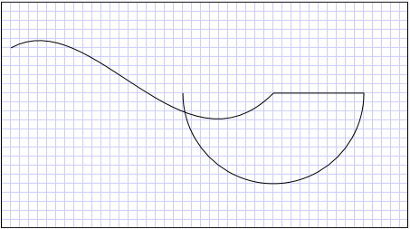
路径几何
<Path Stroke="Black" StrokeThickness="1" >
  <Path.Data>
    <PathGeometry>
      <PathGeometry.Figures>
        <PathFigure StartPoint="10,50">
          <PathFigure.Segments>
            <BezierSegment
              Point1="100,0"
              Point2="200,200"
              Point3="300,100"/>
            <LineSegment Point="400,100" />
            <ArcSegment
              Size="50,50" RotationAngle="45"
              IsLargeArc="True" SweepDirection="Clockwise"
              Point="200,100"/>
          </PathFigure.Segments>
        </PathFigure>
      </PathGeometry.Figures>
    </PathGeometry>
  </Path.Data>
</Path>
// Create a figure.
PathFigure myPathFigure = new PathFigure();
myPathFigure.StartPoint = new Point(10,50);
myPathFigure.Segments.Add(
    new BezierSegment(
        new Point(100,0),
        new Point(200,200),
        new Point(300,100),
        true /* IsStroked */  ));
myPathFigure.Segments.Add(
    new LineSegment(
        new Point(400,100),
        true /* IsStroked */ ));
myPathFigure.Segments.Add(
    new ArcSegment(
        new Point(200,100),
        new Size(50,50),
        45,
        true, /* IsLargeArc */
        SweepDirection.Clockwise,
        true /* IsStroked */ ));

/// Create a PathGeometry to contain the figure.
PathGeometry myPathGeometry = new PathGeometry();
myPathGeometry.Figures.Add(myPathFigure);

// Display the PathGeometry.
Path myPath = new Path();
myPath.Stroke = Brushes.Black;
myPath.StrokeThickness = 1;
myPath.Data = myPathGeometry;
' Create a figure.
Dim myPathFigure As New PathFigure()
myPathFigure.StartPoint = New Point(10,50)
myPathFigure.Segments.Add(New BezierSegment(New Point(100,0), New Point(200,200), New Point(300,100), True)) ' IsStroked
myPathFigure.Segments.Add(New LineSegment(New Point(400,100), True)) ' IsStroked
myPathFigure.Segments.Add(New ArcSegment(New Point(200,100), New Size(50,50), 45, True, SweepDirection.Clockwise, True)) ' IsStroked  -  IsLargeArc

''' Create a PathGeometry to contain the figure.
Dim myPathGeometry As New PathGeometry()
myPathGeometry.Figures.Add(myPathFigure)

' Display the PathGeometry.
Dim myPath As New Path()
myPath.Stroke = Brushes.Black
myPath.StrokeThickness = 1
myPath.Data = myPathGeometry
通过使用一个PathGeometry中的多个PathFigure对象,可以创建更复杂的几何图形。
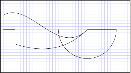
以下示例创建一个PathGeometry,其中包含两个PathFigure对象,每个PathFigure对象又包含多个PathSegment对象。 使用上面示例中的PathFigure以及带有PathFigure、PolyLineSegment和QuadraticBezierSegment的。 A PolyLineSegment 使用点数组进行定义,QuadraticBezierSegment 使用控制点和终点来定义。 下图显示了此示例创建的形状。
 包含
包含
包含多个图形的 PathGeometry
<Path Stroke="Black" StrokeThickness="1" >
  <Path.Data>
    <PathGeometry>
      <PathGeometry.Figures>
        <PathFigure StartPoint="10,50">
          <PathFigure.Segments>
            <BezierSegment
              Point1="100,0"
              Point2="200,200"
              Point3="300,100"/>
            <LineSegment Point="400,100" />
            <ArcSegment
              Size="50,50" RotationAngle="45"
              IsLargeArc="True" SweepDirection="Clockwise"
              Point="200,100"/>
          </PathFigure.Segments>
        </PathFigure>

        <PathFigure StartPoint="10,100">
          <PathFigure.Segments>
            <PolyLineSegment Points="50,100 50,150" />
            <QuadraticBezierSegment Point1="200,200" Point2="300,100"/>
          </PathFigure.Segments>
        </PathFigure>
      </PathGeometry.Figures>
    </PathGeometry>
  </Path.Data>
</Path>
PathGeometry myPathGeometry = new PathGeometry();

// Create a figure.
PathFigure pathFigure1 = new PathFigure();
pathFigure1.StartPoint = new Point(10,50);
pathFigure1.Segments.Add(
    new BezierSegment(
        new Point(100,0),
        new Point(200,200),
        new Point(300,100),
        true /* IsStroked */ ));
pathFigure1.Segments.Add(
    new LineSegment(
        new Point(400,100),
        true /* IsStroked */ ));
pathFigure1.Segments.Add(
    new ArcSegment(
        new Point(200,100),
        new Size(50,50),
        45,
        true, /* IsLargeArc */
        SweepDirection.Clockwise,
        true /* IsStroked */ ));
myPathGeometry.Figures.Add(pathFigure1);

// Create another figure.
PathFigure pathFigure2 = new PathFigure();
pathFigure2.StartPoint = new Point(10,100);
Point[] polyLinePointArray =
    new Point[]{ new Point(50, 100), new Point(50, 150)};
PolyLineSegment myPolyLineSegment = new PolyLineSegment();
myPolyLineSegment.Points =
    new PointCollection(polyLinePointArray);
pathFigure2.Segments.Add(myPolyLineSegment);
pathFigure2.Segments.Add(
    new QuadraticBezierSegment(
        new Point(200,200),
        new Point(300,100),
        true /* IsStroked */ ));
myPathGeometry.Figures.Add(pathFigure2);

// Display the PathGeometry.
Path myPath = new Path();
myPath.Stroke = Brushes.Black;
myPath.StrokeThickness = 1;
myPath.Data = myPathGeometry;
Dim myPathGeometry As New PathGeometry()

' Create a figure.
Dim pathFigure1 As New PathFigure()
pathFigure1.StartPoint = New Point(10,50)
pathFigure1.Segments.Add(New BezierSegment(New Point(100,0), New Point(200,200), New Point(300,100), True)) ' IsStroked
pathFigure1.Segments.Add(New LineSegment(New Point(400,100), True)) ' IsStroked
pathFigure1.Segments.Add(New ArcSegment(New Point(200,100), New Size(50,50), 45, True, SweepDirection.Clockwise, True)) ' IsStroked  -  IsLargeArc
myPathGeometry.Figures.Add(pathFigure1)

' Create another figure.
Dim pathFigure2 As New PathFigure()
pathFigure2.StartPoint = New Point(10,100)
Dim polyLinePointArray() As Point = { New Point(50, 100), New Point(50, 150)}
Dim myPolyLineSegment As New PolyLineSegment()
myPolyLineSegment.Points = New PointCollection(polyLinePointArray)
pathFigure2.Segments.Add(myPolyLineSegment)
pathFigure2.Segments.Add(New QuadraticBezierSegment(New Point(200,200), New Point(300,100), True)) ' IsStroked
myPathGeometry.Figures.Add(pathFigure2)

' Display the PathGeometry.
Dim myPath As New Path()
myPath.Stroke = Brushes.Black
myPath.StrokeThickness = 1
myPath.Data = myPathGeometry
StreamGeometry
与 PathGeometry 类相似,StreamGeometry 定义可能包含曲线、弧线和线条的复杂几何形状。 与 PathGeometry 不同,StreamGeometry 的内容不支持数据绑定、动画或修改。 如果需要描述复杂的几何图形,但不希望承担数据绑定、动画或修改相关的开销,请使用 StreamGeometry。 由于其效率,类 StreamGeometry 是描述装饰器的好选择。
有关示例,请参阅 使用 StreamGeometry 创建形状。
路径标记语法
这些 PathGeometry 和 StreamGeometry 类型支持使用特殊系列移动和绘制命令的可扩展应用程序标记语言(XAML)属性语法。 有关详细信息,请参阅 路径标记语法。
复合几何图形
可以使用GeometryGroup、CombinedGeometry或调用静态Geometry方法Combine来创建复合几何图形对象。
该 CombinedGeometry 对象和 Combine 方法执行布尔运算以合并由两个几何图形定义的区域。 Geometry 没有区域的对象将被丢弃。 只能组合两个 Geometry 对象(尽管这两个几何图形也可能是复合几何图形)。
GeometryGroup 类会创建它所包含的 Geometry 对象的集合体,但不会合并它们的区域。 可以向GeometryGroup添加任意数量的Geometry对象。 有关示例,请参阅 “创建复合形状”。
由于它们不执行组合作,因此使用 GeometryGroup 对象比使用 CombinedGeometry 对象或 Combine 方法具有性能优势。
组合几何图形
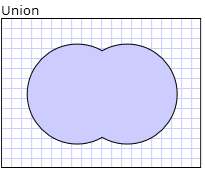
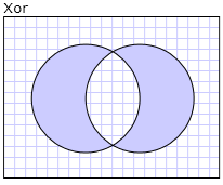
前面的部分提到 CombinedGeometry 对象和 Combine 方法合并了它们所包含的几何图形定义的区域。 GeometryCombineMode枚举指定如何组合几何图形。 属性的可能值为GeometryCombineMode、Union、Intersect、Exclude和Xor。
在以下示例中,使用联合的组合模式定义 a CombinedGeometry 。 Geometry1 和 Geometry2 都定义为同一半径的圆圈,但中心偏移量为 50。
<Path Stroke="Black" StrokeThickness="1" Fill="#CCCCFF">
  <Path.Data>

    <!-- Combines two geometries using the union combine mode. -->
    <CombinedGeometry GeometryCombineMode="Union">
      <CombinedGeometry.Geometry1>
        <EllipseGeometry RadiusX="50" RadiusY="50" Center="75,75" />
      </CombinedGeometry.Geometry1>
      <CombinedGeometry.Geometry2>
        <EllipseGeometry RadiusX="50" RadiusY="50" Center="125,75" />
      </CombinedGeometry.Geometry2>
    </CombinedGeometry>
  </Path.Data>
</Path>
在下面的示例中,使用组合模式Xor定义 aCombinedGeometry。 Geometry1 和 Geometry2 都定义为同一半径的圆圈,但中心偏移量为 50。
<Path Stroke="Black" StrokeThickness="1" Fill="#CCCCFF">
  <Path.Data>

    <!-- Combines two geometries using the XOR combine mode. -->
    <CombinedGeometry GeometryCombineMode="Xor">
      <CombinedGeometry.Geometry1>
        <EllipseGeometry RadiusX="50" RadiusY="50" Center="75,75" />
      </CombinedGeometry.Geometry1>
      <CombinedGeometry.Geometry2>
        <EllipseGeometry RadiusX="50" RadiusY="50" Center="125,75" />
      </CombinedGeometry.Geometry2>
    </CombinedGeometry>
  </Path.Data>
</Path>
有关其他示例,请参阅 “创建复合形状 ”和 “创建组合几何图形”。
可冻结特性
由于它继承自 Freezable 类,因此该 Geometry 类提供了几个特殊功能: Geometry 对象可以声明为 XAML 资源,在多个对象之间共享,进行只读,以提高性能、克隆和使线程安全。 有关 Freezable 对象所提供的各种功能的更多信息,请参阅 Freezable 对象概述。
其他几何特征
该 Geometry 类还提供有用的实用工具方法,例如:
FillContains - 确定几何图形是否包含另一个 Geometry。
StrokeContains - 确定Geometry的路径是否包含指定的点。
请参阅Geometry类以获取其方法的完整列表。
